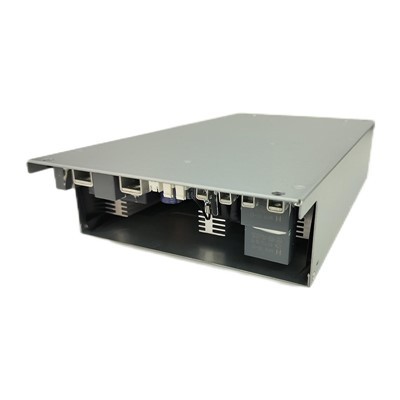


60W PoE Injector - 2.5G Single-Port PoE++
The TPT60S54A 60W PoE injector is a single-port midspan: data from any switch, 54 V DC from the mains, merged onto one cable. A full 60 W (54 V / 1.1 A) at the output - enough for a heated PTZ, a tri-band Wi-Fi 7 access point or a 55-inch signage panel where no AC outlet exists.
Installation is two patch cords and an AC lead: no configuration, no driver, no PoE switch. The unit detects and classifies 802.3bt, 802.3at and 802.3af devices before applying voltage, and the passive data path carries 100 / 1000 / 2500 Mbps over runs up to 100 m - so a 2.5G camera is not capped by its power supply.
Built as a 60 W supply, not a 30 W board pushed harder: ±3% line, load and accuracy, ≤ 500 mVp-p ripple, 82% efficiency at 230 Vac. That keeps it fanless and ventilated, rated −10 to +50 ℃ continuous, in a 94V-0 housing of 136 × 58 × 34.8mm and 221g.
3000 Vac input-to-output isolation, 8 kV contact / 15 kV air ESD, 2 kV common-mode surge and EN 55032 Class B emissions. Over-current, over-voltage and short circuit all recover automatically in hiccup mode.
Typical fit: outdoor PTZ with heater and IR · Wi-Fi 6E/7 access points · 40–60 W signage · 5G small cells · machine-vision camera.
Typical fit:
outdoor PTZ with heater and IR · Wi-Fi 6E/7 access points · 40–60 W signage · 5G small cells · machine-vision cameras

802.3bt
PoE standard
54 V / 1.1 A
Output
2.5 Gbps
Data pass-through
60 W
Output power
Key Features
Six things that separate this 60W midspan from a generic brick
A real 60 W budget
54 V / 1.1 A delivers 59.4 W at the injector - enough for outdoor PTZ cameras running IR and heater duty cycles, tri-band Wi-Fi 6E/7 APs, PoE lighting controllers and large-format signage panels.
2.5G, end to end
100/1000/2500 Mbps auto-negotiation on a fully passive data path. A 60 W device is usually a multi-gig device too - this unit will not quietly drop it back to Gigabit or 100 Mbps.
±3% regulation, not ±5%
Line, load and output accuracy are all held to ±3%, with overshoot limited to ±3% across a 0–1.1 A step. Stable rails mean stable behaviour when a camera's load jumps by 30 W in a millisecond.
Fanless at 60 W
82% efficiency at 230 Vac keeps dissipation low enough for natural convection in a ventilated 94V-0 PC housing - rated to +50 ℃ ambient, with no fan to seize and no filter to service.
Isolation and surge built for outdoors
3000 Vac input-to-output, 8 kV contact / 15 kV air ESD and 2 kV common-mode surge immunity. When the cable leaves the building, this is the difference between a nuisance trip and a dead port.
221 g, same footprint family
136 × 58 × 34.8 mm with ±1 mm tolerance, PC housing, RoHS/REACH compliant. Mounts beside a camera pole box, on a DIN-rail tray or inside a small wall enclosure.
Applications
30 W covers a standard dome or a dual-band AP. 60 W is for devices that spike, or that run accessories on the same cable.
These are the six deployments our customers specify this model for.

Outdoor PTZ with heater and IR
Pan-tilt-zoom heads with wipers, blowers and 100 m IR arrays routinely pull 40–55 W in cold weather. A 60 W budget keeps the camera panning instead of rebooting when the heater engages.

Wi-Fi 6E / 7 access points
Tri-band APs with 2.5G or 5G uplinks exceed 30 W once all radios are active. Feeding one from a 60 W injector preserves the multi-gig backhaul the AP was bought for.

Digital signage and outdoor displays
Menu boards, wayfinding panels and window displays in the 40–60 W range, mounted where a power drop would mean chasing a wall. One cable serves both content and power.

5G small cells and wireless bridges
Street-level small cells, CPE radios and point-to-point bridges are typically fed by a single Ethernet drop and need more headroom than PoE+ gives. The injector removes the local AC feed.

Machine vision and rugged terminals
High-frame-rate vision cameras, industrial panel PCs and gateways on the plant floor, where 3000 Vac isolation and IEC 61000-4 immunity matter as much as wattage.
PoE lighting and building controllers
PoE luminaires, blind and HVAC controllers, access-control nodes with heaters - retrofits where pulling mains cable is the expensive part of the project.

Installation
Four steps to install - and what the two LEDs tell you
1. Patch the switch port to DATA IN - data only, from any standard Ethernet port.
2. Patch DATA & POWER OUT to the powered device (PoE out on pins 1/2, 4/5 positive; 3/6, 7/8 negative).
3. Connect the AC lead - 90–264 Vac, no selection or setting required.
4. Check the two front LEDs: detection and classification complete within seconds.
| Indicator | State | What it means |
|---|---|---|
| AC LED (φ3 green) | On | Mains is present on the input side. |
| AC LED (φ3 green) | Off | No input power - check the outlet and the input fuse (T3.15 A / 250 Vac). |
| PORT LED (φ3 green) | On | The device passed IEEE detection and classification; 54 V DC is being delivered. |
| PORT LED (φ3 green) | Off | The far end did not present a valid PoE signature - a non-PoE device, a faulty patch lead or the wrong port. |
FAQ
01. What devices need a 60W PoE injector rather than 30 W?
02. Is 60 W "PoE+" or "PoE++"?
03. Does it deliver 60 W over two pairs or four?
04. Will it work with my non-PoE switch?
05. Does 60 W make the unit hot or noisy?
Injector or Switch?
Buyers often start by searching for a "60W PoE switch" when what they actually need is one powered port.
The two solve different problems - pick by device count, not by wattage.

- 1 powered port - exactly one device, one run
- No rack space, no configuration, plug and play
- Lowest cost per powered port for 1–2 devices
- Ideal for retrofits and long single runs
- Cannot manage VLANs, QoS or per-port power budgets
- 4–24 powered ports with a shared power budget
- Per-port monitoring, VLANs, remote reboot
- Best when an entire floor or camera group is powered
- Requires rack or cabinet space and configuration
- Higher upfront cost - pays off above ~4 ports

Rule of thumb: one or two devices → injector. Four or more on the same segment, or you need management → switch. Many projects use both.
Hot Tags: 60W PoE Injector, China 60W PoE Injector manufacturers, suppliers, factory, Ethernet POE Power Supply, 802 3bt 90W POE, 90W POE Injector, IEEE 802 3 at POE , 60W POE Switch, poe power supply
Product Specification
| Item | Specification |
|---|---|
| PoE Channel | |
| Model | TPT60S54A-01-TN |
| Format | Single-port midspan injector, 2.5G data pass-through, 60 W PoE budget |
| Standard compliance | IEEE 802.3bt Type 3 class; interoperates with 802.3at and 802.3af endpoints; injected line stays standard-compliant |
| Data path | 100 / 1000 / 2500 Mbps auto-negotiation, fully passive |
| Connectors | Two RJ45: DATA IN (data only) and DATA & POWER OUT (data + power on two pairs) |
| PoE pinout | Pins 1/2 and 4/5 positive; pins 3/6 and 7/8 negative |
| Thermal design | Fanless, natural convection |
| Substance compliance | RoHS / REACH |
| AC Side | |
| AC input range | 90 to 264 Vac |
| Rated input | 100–240 Vac, 47–63 Hz |
| Input current | 1.5 A maximum at full load |
| Cold-start inrush | 80 A peak or less, measured at 230 Vac |
| Conversion efficiency | 82% at 230 Vac, full load |
| Earth leakage | Below 3.5 mA at 230 Vac |
| Internal fuse | T3.15 A / 250 Vac |
| DC Output | |
| Output rail | 54 V DC, staying within 51.3–56.7 V across 100–240 Vac input at 1.1 A |
| Output current | 0 to 1.1 A over the full input range |
| Continuous power | 60 W maximum |
| Line regulation | ±3% maximum, 100–240 Vac input at 1.1 A |
| Load regulation | ±3% maximum, 100–240 Vac input at 1.1 A |
| Set-point accuracy | ±3% maximum, 100–240 Vac input at 1.1 A |
| Ripple & noise | 500 mVp-p or less at 25 ℃, 20 MHz bandwidth (0.1 µF ceramic plus 10 µF electrolytic bypass at the connector) |
| Dynamic load response | Recovers within 54 V ±3% at 0.2 A/µs slew for 25→50% and 50→75% load steps |
| Overshoot | Within ±3% across a 0–1.1 A step |
| Power-on time | 3 s or less from 230 Vac at full load |
| Hold-up time | 10 ms or more at 100 Vac, 1.1 A |
| Output rise time | 30 ms or less (10–90% of Vo at 1.1 A) |
| Fault Behaviour | |
| Over-current trip | Between 1.1 and 1.5 A; hiccup mode, restarts automatically |
| Short circuit | Hiccup mode; output resumes once the fault clears |
| Over-voltage trip | Trips between 58 and 63 V; hiccup mode, automatic recovery |
| Isolation & Safety | |
| Isolation resistance | 100 MΩ or more, measured at 500 VDC (25 ℃ / 70% RH), primary to secondary |
| Hi-pot test | Primary–secondary 3000 Vac / 10 mA / 3 s · primary–earth 1500 Vac / 10 mA / 1 min · secondary–earth 500 Vac / 10 mA / 1 min, with no breakdown or flashover |
| Safety design basis | Designed to the requirements of UL 62368 and EN 62368 |
| Environment & Build | |
| Operating ambient | −10 ℃ to +50 ℃ at full load |
| Storage | −20 ℃ to +85 ℃ |
| Humidity | 10–90% RH operating · 5–95% RH storage, non-condensing |
| Max altitude | 10,000 ft (about 3,000 m) operating · 20,000 ft storage |
| MTBF | Over 27,000 hours at 40 ℃ - consistent with the roughly three-year service life of the electrolytic capacitors |
| Vibration test | 10–55 Hz at 49.0 m/s² (5G), 60 minutes per axis, X/Y/Z |
| Shock test | 196.1 m/s² (20G) for 11 ms, one shock per axis |
| Enclosure size | 136 × 58 × 34.8 mm, tolerance ±1 mm |
| Net weight | 221 g |
| Housing material | Flame-retardant polycarbonate, UL 94V-0 |
| Front-panel LEDs | Two φ3 mm green indicators: AC (mains present) and PORT (PoE delivery active) |