

Which Components Directly Determine the Lifespan of a Power Adapter?
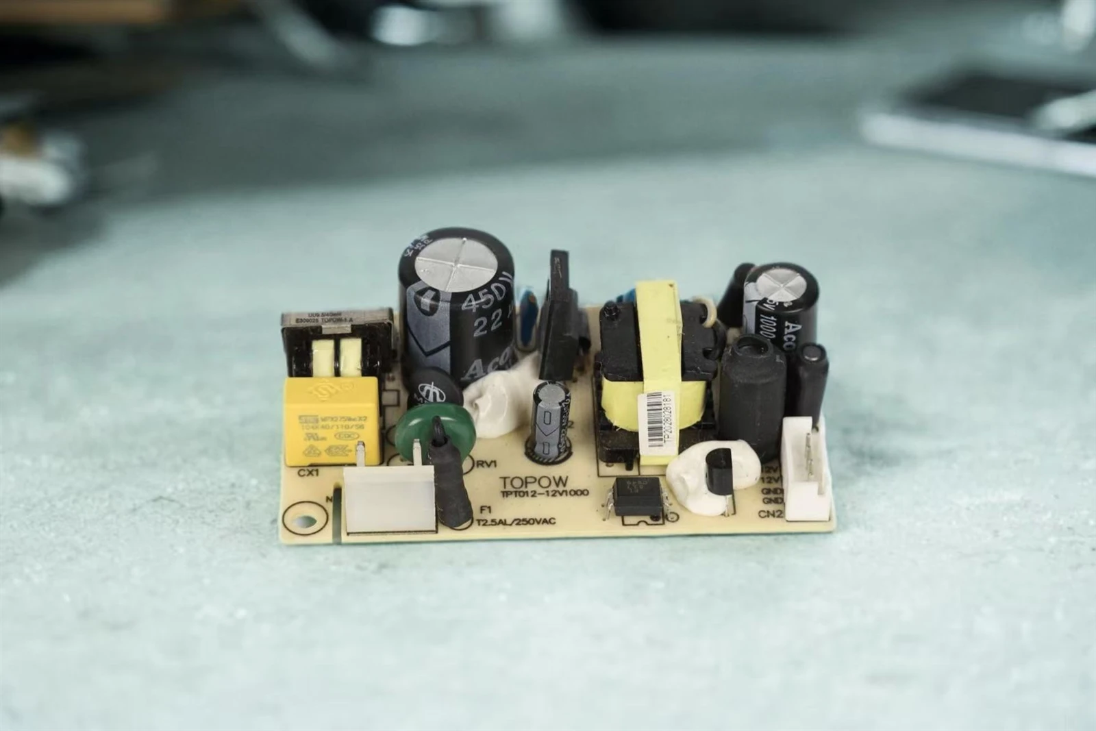
Introduction
A power adapter may appear to be a simple black box that converts AC to DC, but its actual lifespan is determined by the hidden "life meters" inside - a handful of critical components that age over time. While all electronic components eventually degrade, certain parts are significantly more vulnerable than others. Understanding which components are the "weakest links" helps both OEMs in design selection and end-users in proper usage.
This article reveals the key components that directly influence adapter longevity, explains how they fail, and provides actionable guidance for extending service life.
1. Core Components with Direct Impact on Lifespan
1.1 Electrolytic Capacitors (The Most Critical and Vulnerable Component)
Failure Mechanism: Electrolytic capacitors contain a liquid electrolyte that gradually evaporates over time and with heat. As the electrolyte dries out, capacitance decreases and Equivalent Series Resistance (ESR) increases.
Typical Symptoms: Increased output ripple, unstable voltage, output voltage rising under no-load or light-load conditions, and eventual complete failure to power the device.
Life Rule: Electrolytic capacitor life follows the Arrhenius Law - for every 10°C increase in temperature, the capacitor's lifespan is cut in half. High-quality adapters use 105°C high-temperature, long-life electrolytic capacitors, while inferior ones may use 85°C parts that degrade much faster.
What to look for: Rated temperature (105°C preferred) and rated lifetime hours (e.g., 2,000h, 5,000h, or 10,000h at rated temperature).
1.2 Power Switching MOSFETs
Failure Mechanisms:
- Thermal stress: Long-term operation at high temperatures can cause package material aging and solder joint cracking
- Electrical stress: Voltage/current spikes during switching transitions can cause avalanche breakdown or gradual performance degradation
Results: Increased on-resistance (Rds(on)), higher switching losses, reduced efficiency, and in severe cases, short-circuit failure that may damage other components.
What to look for: MOSFETs with appropriate voltage derating (typically ≥ 1.5× the actual operating voltage) and low thermal resistance packaging.
1.3 High-Frequency Transformer
Failure Mechanisms:
- Insulation aging: The enamel insulation on winding wires degrades under combined heat and voltage stress, potentially leading to inter-winding shorts
- Core loss heating: Magnetic core heating at high frequencies can, over time, alter the magnetic properties of the ferrite material
Results: Audible noise (buzzing), reduced efficiency, and in worst cases, primary-to-secondary breakdown that creates a serious safety hazard.
What to look for: Transformers with Class B (130°C) or higher insulation systems, and proper margin between windings.
1.4 Optocoupler (Feedback Isolation)
Failure Mechanism: The internal LED within the optocoupler gradually loses luminous efficiency over time - a phenomenon known as current transfer ratio (CTR) degradation. As the LED dims, the feedback signal weakens.
Results: Unstable feedback signals, drifting output voltage, and compromised loop control - all of which can make the adapter's output unpredictable.
What to look for: Optocouplers with high initial CTR and low degradation rates from reputable brands.
1.5 Rectifier Diodes (Input Bridge Rectifier and Output Rectifier)
Failure Mechanisms: Long-term exposure to reverse recovery current and thermal dissipation gradually degrades the PN junction characteristics.
Results: Increased forward voltage drop (Vf), higher heat generation, reduced efficiency, and in severe cases, thermal runaway and catastrophic failure.
What to look for: Schottky diodes or fast-recovery diodes with adequate voltage and current margins, and low thermal resistance.
1.6 PCB (Printed Circuit Board)
Failure Mechanisms:
- Thermal cycling fatigue: Repeated expansion and contraction as the board heats and cools can cause pad or trace cracking - especially problematic for large components
- Moisture and contamination: In harsh environments, creepage corrosion or reduced insulation resistance can lead to leakage currents or short circuits
What to look for: High-Tg (glass transition temperature) PCB material (≥ 150°C), with proper creepage distances and conformal coating for harsh environments.
2. External Factors That Accelerate Component Aging
| Factor | Impact |
|---|---|
| High ambient temperature | The #1 killer - every 10°C rise halves the life of electrolytic capacitors and accelerates aging of all semiconductors |
| Frequent plugging/unplugging | Mechanical stress damages AC inlet connectors, DC plugs, and PCB solder joints |
| Power grid fluctuations and surges | Voltage spikes or lightning surges can instantly destroy input fuses, MOVs (varistors), and bridge rectifiers |
| Load mismatch (overload) | Forcing components to operate at or beyond their limits accelerates degradation across the entire system |
| Poor ventilation | Trapped heat accelerates all failure mechanisms simultaneously - a compounding effect |
3. How to Extend Adapter Lifespan: Design and Usage Recommendations
| Level | Specific Measures |
|---|---|
| Manufacturer Design | Select industrial-grade, long-life components; optimize thermal design (thermal pads, larger heatsinks, adequate ventilation); implement 100% burn-in and aging testing; apply conformal coating for protection |
| User Operation | Keep the adapter in well-ventilated areas; avoid high-temperature and humid environments; unplug gently by pulling the plug, not the cable; avoid continuous overload operation; unplug when not in use for extended periods |
Conclusion
The lifespan of a power adapter is essentially a race against heat and time. Among all components, the electrolytic capacitor is the most common bottleneck - it is almost always the first component to fail in an aging adapter. Power semiconductors (MOSFETs and diodes) and the transformer determine the risk of catastrophic failure.
A well-designed, properly built adapter with premium components can achieve a service life of 30,000 to 50,000 hours (roughly 3 to 5+ years under normal use). In contrast, a poorly made adapter may fail within the first year due to early failure of a single critical component - often an underspecified electrolytic capacitor or MOSFET.
For OEMs, investing in quality components and thorough thermal validation is not an expense - it is insurance against field failures and warranty claims.
For end users, choosing a reputable brand and maintaining good operating conditions are the most effective ways to maximize adapter lifespan.

Designed for Longevity - TOPOW's Quality Commitment
TOPOW Electronics designs power adapters with industrial-grade electrolytic capacitors, robust MOSFET derating, and comprehensive thermal management. All products undergo 100% burn-in testing to ensure long-term reliability. For more information on our quality-focused design approach, please contact us.


