

Power Adapter Output Cable Specifications and Selection
When selecting a power adapter, the output cable (DC cord) is often the most overlooked aspect. Many engineers and procurement professionals focus on voltage, current, certifications, and other core parameters, neglecting this seemingly minor cable - yet it is precisely the "last meter" connecting the adapter to the device, and its specifications directly affect power quality and long-term reliability.
A substandard output cable can cause insufficient voltage at the device end, unstable operation, or even safety hazards due to overheating. This article systematically covers four key dimensions of output cable selection: wire gauge, length, shielding, and temperature rating.
1. Wire Gauge (AWG): Diameter Determines Current Capacity
AWG (American Wire Gauge) is the standard for measuring wire thickness. The smaller the AWG number, the thicker the wire, and the higher the current-carrying capacity.
| AWG | Cross-Section (mm²) | Recommended Current (A) | Application |
|---|---|---|---|
| 18AWG | 0.82 | 5-7A | High-power adapters (60W+) |
| 20AWG | 0.52 | 3-5A | Medium-power adapters (30-60W) |
| 22AWG | 0.32 | 2-3A | Low-power adapters (<30W) |
| 24AWG | 0.20 | 1-2A | Very low-power devices |
Selection Principle: The wire gauge must ensure that temperature rise remains within acceptable limits at maximum output current. Rule of thumb: cable current rating should be ≥ 1.2× the adapter's rated output current to provide headroom for peak loads.
2. Length: The Hidden Culprit of Voltage Drop
Cable length directly affects the actual voltage at the output end. When current flows through a conductor, voltage drop occurs (V = I × R). The longer the cable, the higher the resistance, and the more significant the voltage drop.
Example: Using 22AWG cable (resistance ≈ 53Ω/km), length 1.8m, output current 2A:
- Single conductor resistance = 53Ω/km × 1.8m = 0.095Ω
- Total resistance for positive and negative conductors ≈ 0.19Ω
- Voltage drop = 2A × 0.19Ω = 0.38V
For a 5V adapter, a 0.38V drop means the device receives only 4.62V - potentially below the device's minimum operating voltage, causing abnormal behavior.
Selection Principle:
- For every additional 1 meter of cable length, increase the wire gauge by one step (lower AWG number) .
- For long-distance runs (3+ meters), prefer thicker gauges (18AWG or lower), or consider implementing Remote Sense voltage compensation at the device side.
3. Shielding: The "Protective Armor" Against Interference
In industrial environments or communication equipment with complex electromagnetic conditions, shielding design for output cables is critical.
| Shielding Type | Characteristics | Applications |
|---|---|---|
| Unshielded | Lowest cost, suitable for general consumer electronics | Home routers, low-power devices |
| Foil Shield | Moderate suppression of high-frequency interference | Moderate EMI environments |
| Braided Shield | Good shielding effectiveness, flexible | Industrial, telecom, medical equipment |
| Foil + Braided Double Shield | Optimal shielding performance | EMC-critical applications |
Selection Principle: If the device is EMC-sensitive (e.g., telecom equipment, medical instruments), or operates near strong interference sources like VFDs or high-power motors, shielded cables should be prioritized - with the shield reliably grounded at the adapter end.
4. Temperature Rating: The Foundation of Environmental Adaptability
The insulation material determines the cable's operating temperature range.
| Material | Temperature Rating | Characteristics | Applications |
|---|---|---|---|
| PVC | -20°C ~ +80°C | Low cost, good flexibility | General consumer electronics |
| Cross-linked PE | -40°C ~ +125°C | High temperature resistance, anti-aging | Industrial power, outdoor equipment |
| Silicone Rubber | -60°C ~ +200°C | Extremely wide range, flexible but less abrasion-resistant | Special environments (e.g., high-temperature ovens) |
| TPE | -40°C ~ +105°C | Flexible, cold-resistant, halogen-free | Premium consumer electronics, power tools |
Selection Principle: The cable's temperature rating should cover the device's operating temperature range with margin. Particularly, cables generate self-heating under full load, so when used in high-temperature environments, higher-rated cables are recommended.
5. Other Key Selection Dimensions
| Dimension | Key Considerations |
|---|---|
| Certifications | Cable should carry safety certifications such as UL / CUL / TÜV (e.g., UL 2464 / UL 2725) to meet system-level certification requirements |
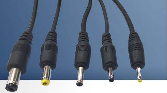
| Connector Specifications | DC barrel connector OD×ID (e.g., 5.5×2.1mm, 5.5×2.5mm) and center polarity must precisely match the device port |
| Tensile Strength | For frequent plugging/unplugging, choose molded strain-relief or overmolded connectors to enhance bend resistance |
| Environmental Compliance | Verify RoHS and Reach compliance, especially for exports to the EU market |
Conclusion
Though small, the output cable carries the adapter's entire output energy. Improper selection can lead to excessive voltage drop, operational instability, EMC test failures, and even safety risks. When selecting a power adapter, be sure to consider the four key factors - wire gauge, length, shielding, and temperature rating - as part of your comprehensive evaluation.
TOPOW Electronics offers end-to-end services from cable selection advice to customized output cable configurations. Our adapters can be flexibly configured with different wire gauges, lengths, connectors, and shielding options to meet customer needs, ensuring stable and reliable power delivery from the adapter to the device.


