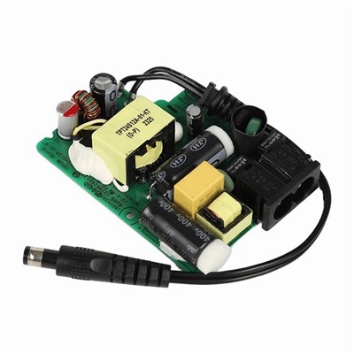

Proper grounding is a critical aspect of ensuring the safety, reliability, and performance of a PCB mount power supply. As a supplier of PCB Mount Power Supply, I understand the importance of this process and have gathered some key insights to share with you.
Understanding the Basics of Grounding
Grounding serves several essential functions in a power supply system. Firstly, it provides a low - impedance path for fault currents to flow safely to the earth. This helps protect users from electric shock in case of insulation failure or other electrical faults. Secondly, grounding helps reduce electromagnetic interference (EMI) and radio - frequency interference (RFI). By providing a reference potential, it can minimize the coupling of unwanted signals between different parts of the circuit.
In a PCB mount power supply, the ground plane is a crucial component. It is a large area of copper on the PCB that is connected to the ground terminal. The ground plane acts as a common reference point for all the electrical signals in the circuit and helps in distributing the return currents evenly.
Design Considerations for Grounding
Ground Plane Layout
When designing the PCB for a power supply, the layout of the ground plane is of utmost importance. The ground plane should be continuous and cover as much of the PCB area as possible. This helps in reducing the resistance and inductance of the ground path. Avoid creating narrow traces or gaps in the ground plane, as these can increase the impedance and lead to signal integrity issues.
For high - current circuits, such as those in an AC - DC Switching Power Supply, it is advisable to use a thicker copper layer for the ground plane. This can handle the large currents without excessive voltage drops.
Separation of Grounds
In some power supply designs, it may be necessary to separate different types of grounds. For example, in a medical power supply like a Medical Open - Frame Power Supply, the analog ground and the digital ground may need to be separated to prevent interference between the sensitive analog circuits and the noisy digital circuits.
However, these separate grounds should be connected at a single point, known as the single - point ground (SPG). This helps in avoiding ground loops, which can cause unwanted noise and interference in the circuit.
Component Placement
The placement of components on the PCB also affects the grounding. Components that generate a lot of heat or noise, such as switching regulators and power transistors, should be placed away from sensitive components. Additionally, these components should be connected to the ground plane in a way that minimizes the length of the ground traces.
Installation and Assembly
Mounting the Power Supply
When mounting the PCB mount power supply, it is essential to ensure good electrical contact between the power supply and the ground plane of the PCB. This can be achieved by using appropriate mounting hardware, such as screws or clips, that are designed to provide a low - resistance connection.
Before mounting the power supply, clean the mounting surface of the PCB to remove any dirt, grease, or oxidation. This helps in ensuring a better electrical connection.


Wiring and Connectors
The wiring used to connect the power supply to other components in the system should be of the appropriate gauge and quality. For high - current applications, use thick wires with low resistance. The connectors used should also be properly rated and have a good contact resistance.
When wiring the power supply, make sure that the ground wires are connected securely and are as short as possible. Long ground wires can introduce inductance, which can cause problems in high - frequency circuits.
Testing and Verification
Continuity Testing
After the power supply is installed on the PCB, perform a continuity test on the ground connections. This can be done using a multimeter to measure the resistance between different points on the ground plane and the ground terminal of the power supply. The resistance should be very low, typically in the milliohm range.
EMI/RFI Testing
Conduct EMI/RFI testing to ensure that the grounding is effective in reducing interference. This can be done using specialized test equipment, such as an EMI receiver. The power supply should meet the relevant electromagnetic compatibility (EMC) standards.
Safety Testing
Safety testing is also crucial to ensure that the grounding provides adequate protection against electric shock. This includes tests such as insulation resistance testing and dielectric withstand testing.
Maintenance and Troubleshooting
Regular Inspections
Regularly inspect the power supply and the PCB for any signs of damage or loose connections. Check the mounting hardware, wiring, and connectors to ensure that they are in good condition.
Troubleshooting Grounding Issues
If there are issues with the grounding, such as excessive noise or interference in the circuit, start by checking the continuity of the ground connections. Look for any loose or damaged wires, connectors, or components.
If the problem persists, it may be necessary to re - evaluate the PCB design and make any necessary changes to the ground plane layout or component placement.
Conclusion
Proper grounding is essential for the safe and reliable operation of a PCB mount power supply. By following the design, installation, testing, and maintenance guidelines outlined above, you can ensure that your power supply has a proper grounding system.
As a supplier of high - quality PCB mount power supplies, we are committed to providing products that meet the highest standards of safety and performance. If you are interested in purchasing our power supplies or have any questions about grounding or other aspects of power supply design, please feel free to contact us for further discussion and procurement negotiation.
References
- Grob, B., & Weisman, C. (2007). Basic Electronics. McGraw - Hill.
- Montrose, M. I. (2000). Printed Circuit Board Design Techniques for EMC Compliance: A Handbook for Designers. IEEE Press.
- National Electrical Code (NEC), NFPA 70.